


Analysis of a Steel Shaft Failure
The hyperstaticity of the assembly as the root cause of fatigue failure
1. Premise and Failure Identification
The analysis of a recent failure case involving a C45 steel shaft used in a slat conveyor system operating in a sand quarry provided an important lesson on the interactions between design, installation, and operational life. The initial fractographic examination clearly identified the failure mode as fatigue fracture, a phenomenon typically triggered by cyclic loading.
However, the Root Cause Analysis did not attribute the responsibility to nominal dimensioning or material defects, but rather to a structurally unsuitable installation configuration: the hyperstatic mounting.
2. The Mounting Configuration and the Hyperstatic Constraint
The transmission system under examination featured the following architecture:
- A flanged Gearbox Unit rigidly fixed to an auxiliary bearing support.
- The gearbox was driven externally via a belt drive.
This configuration introduces a number of constraints greater than what is strictly necessary for the system's stability, setting up a situation of mechanical hyperstaticity (redundancy). In ideal conditions, the alignment between the gearbox output shaft and the conveyor drive shaft should be perfect.
3. The Genesis of Parasitic Bending Stresses
In practice, perfect alignment is impossible to guarantee due to several factors:
- Manufacturing and Mounting Tolerances: Inevitable differences between components.
- Deformations Under Load: Operational loads, particularly the tension exerted by the belt, causing deflections and displacements.
- Thermal Variations: Expansion or contraction of materials.
The rigid constraint imposed by the flanged mounting prevents the system from compensating for these misalignments through free geometric adaptation. The result is the generation of parasitic cyclic bending stresses at the point of the rigid constraint. These bending moments, although not individually high in magnitude, operated cyclically on the shaft's cross-section.
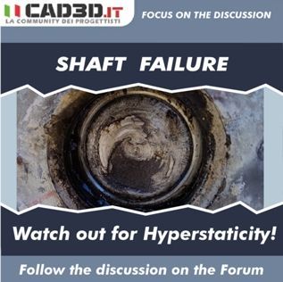
4. The Fatigue Failure Mechanism
The constant and prolonged repetition of these anomalous bending moments exceeded the local fatigue limit of the material (C45 Steel) at the point of highest stress concentration, initiating a micro-crack.
The crack propagated gradually under operational loads, as evidenced by the fracture surface (the polished part), until the shaft's residual resisting cross-section was no longer able to support the load, leading to final instantaneous fracture. It is therefore confirmed that the cause of the failure lies in an anomalous load stemming from the installation, and not in an intrinsic deficiency of the shaft.
5. Recommendations for Correction and Future Reliability
To eliminate hyperstaticity and ensure the system's reliability, it is essential to adopt a solution that guarantees flexible alignment.
The recommended solution is the Shaft-Mounted (or Overhung) Configuration:
- Elimination of Rigid Fixing: The flanged constraint between the gearbox and the support is removed.
- Direct Coupling: The gearbox, in its shaft-mounted version, is keyed directly onto the drive shaft.
- Torque Management: The reaction torque of the gearbox is not rigidly absorbed by the structure, but through a Torque Arm (or Tie Rod/Tensioner).
This torque arm, generally constrained in a semi-floating manner, allows the gearbox body to move slightly and self-align with the shaft axis under load. In this way, the shaft is stressed almost exclusively by the torsional stresses for which it was designed, eliminating the parasitic bending moments and effectively preventing future fatigue failures induced by misalignment.
Follow the discussion: Shaft Failure (https://www.cad3d.it/forum1/discussione/rottura-albero.66995/)